A power bank can supply 9 V or 12 V only when its output port supports that voltage and the connected device or trigger requests it using a compatible charging protocol. A USB connector alone does not tell you which voltages are available.
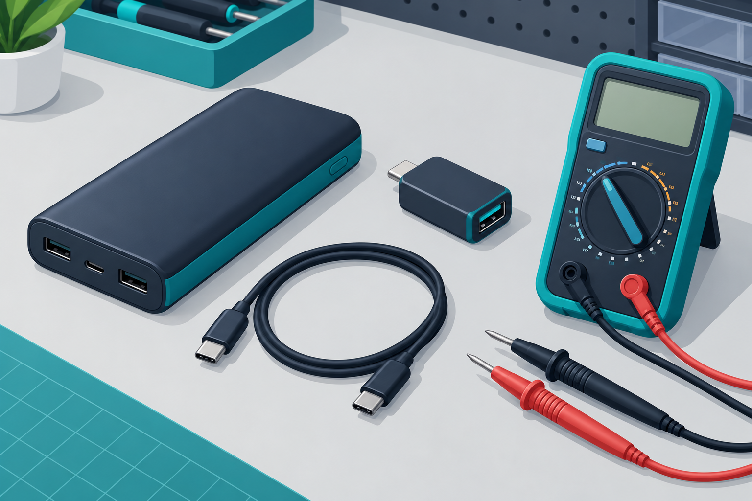
Cover: AI-generated conceptual illustration, not a wiring diagram or evidence of a tested assembly.
Quick Charge and USB Power Delivery are different
Some legacy Quick Charge systems use signalling on the USB D+ and D− lines to request a higher output voltage. USB Power Delivery on USB-C negotiates power over the configuration channel (CC). A resistor-and-diode arrangement intended for one charging method is not a universal substitute for the other.
Texas Instruments’ Quick Charge 2.0 power-supply reference design explains a source that selects 5 V, 9 V or 12 V using a charger-interface IC and D+/D− signalling. Its USB PD power-negotiation guide explains negotiated power contracts. These are explanations of specific protocols, not proof that an arbitrary power bank supports 12 V.
Check these details before choosing a trigger
- Exact output port: read the power bank label and manual for the port you will use. Its USB-A and USB-C ports may have different capabilities.
- Supported voltage: confirm that the requested output is explicitly supported. Do not assume every USB-C PD source offers a fixed 12 V output.
- Available current and power: compare the rating at that voltage with the load’s requirements. A 12 V, 2 A load needs 24 W; a source limited to 12 V, 1.5 A cannot supply that rated load.
- Trigger compatibility: use a documented trigger module matching the source protocol and voltage. Check its output-current limit and what it does if negotiation fails.
- Load compatibility: confirm the device’s allowed input range, connector dimensions and polarity. A connector that fits does not prove electrical compatibility.
Why the earlier resistor-and-diode instructions were removed
A resistor divider does not boost the USB power output. At most, a suitable signalling circuit can ask a compatible source to change its regulated output. The previous version also incorrectly described ordinary diode forward drops as “Zener mode” and did not establish component values, timing or compatibility. Those instructions and their diagrams have been removed rather than presented as a verified build.
Verification sequence
- Keep the load disconnected. Select the desired voltage using the trigger manufacturer’s instructions.
- Connect the trigger to the compatible power-bank port using a suitably rated cable.
- Use a multimeter in DC-voltage mode to check the output voltage and polarity. Keep probes from bridging adjacent contacts. Never place a meter in current mode directly across the output.
- Check operation with an appropriate test load within the ratings of the source, cable and trigger. An unloaded voltage reading alone does not prove that the setup can provide the required current.
- Confirm that reconnecting the cable or restarting the power bank produces the expected output before connecting the intended device. Stop if the output is unstable, the source repeatedly shuts down or parts become abnormally hot.
If the output stays at 5 V
Check protocol compatibility, the selected voltage, the specific port and the cable. A failed request may leave the source at its default output or cause a shutdown. Do not repeatedly modify data-line wiring to force a result. Choose a power source explicitly rated for the required output if the power bank cannot provide it.
Scope of this guide
This is a compatibility and measurement guide, not a tested schematic for a particular power bank. It does not require opening the bank or modifying its lithium cells. For current and power calculations, use the Ohm’s law calculator. Report a correction with the exact power-bank and trigger model through our contact page.