A low-battery indicator warns that the measured battery voltage has crossed a chosen threshold. It does not disconnect the load. This distinction matters: an LED warning alone cannot prevent continued discharge if the equipment stays connected.
LM319 and 555 indicator example
The archived schematic below combines an LM319 comparator, a 555 timer and a 7805 regulator. The comparator senses a divided version of the battery voltage against a reference. Its output controls the timer, which provides a flashing LED indication. The load is not switched by this circuit.
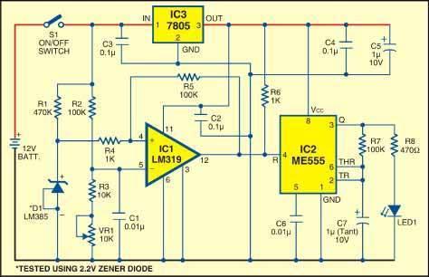
Choosing a warning threshold
Start with the battery manufacturer’s discharge limits for the exact chemistry and cell count. A nominal “12 V” label is not enough to select a safe threshold. Voltage measured under load can differ from the voltage after the battery rests, so record the load conditions when calibrating a warning circuit. Do not use a universal 10 V setting for every battery.
Use an adjustable, current-limited DC supply to test the indicator without intentionally over-discharging a battery. Verify the IC supply ranges and component ratings first. Measure the input with a multimeter, vary the voltage slowly around the desired warning point and record when the LED changes state. Repeat while increasing the voltage. If the indication chatters near the transition, investigate noise, supply decoupling and comparator hysteresis.
What a voltage monitor can tell you
A basic monitor compares a voltage signal with a reference and turns that comparison into an indication. A potentiometer adjusts the trip point; it does not establish battery chemistry or remaining capacity. LED colours are a display choice, so label what each colour means on the finished device. A green LED should never be treated as proof that a battery is healthy or fully charged.
A useful test record includes the supply voltage, load current, trip voltage while falling, recovery voltage while rising and measured standby current. These measurements help distinguish a repeatable warning from an LED that changes unpredictably with the load.
When automatic protection is required
Automatic low-voltage disconnect needs a rated switching stage and a defined reconnect threshold. The switch must handle the load’s normal current and startup surge. A battery-management system may also monitor individual cells, current and temperature. Neither a simple LED monitor nor this archived schematic substitutes for the protection specified by the battery manufacturer.
Before building from the archived drawing, verify every component, pin assignment and reference connection against manufacturer documentation. If you cannot establish a complete, consistent design, use a documented monitor or protection module matched to the battery and load. Send corrections through our contact page, including the component part number and the relevant measurement.