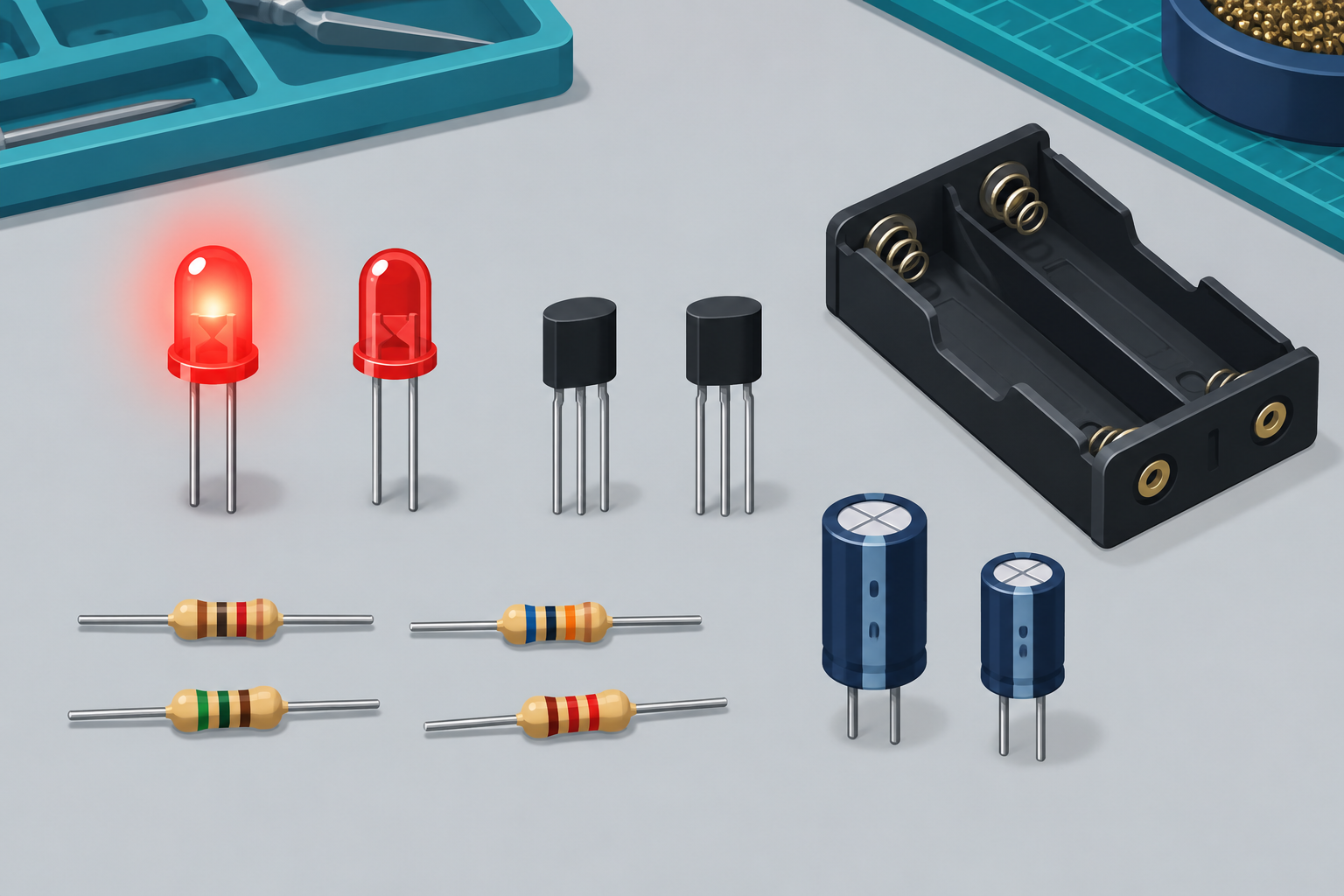
A two-transistor astable multivibrator alternates between two states without a clock input. Each transistor switches one LED, while capacitors couple the two stages. It is often called an LED “flip-flop”, although an astable oscillator keeps switching rather than holding a stable logic state.
The cover is an AI-generated parts illustration, not a wiring diagram. This guide describes a circuit to verify on a breadboard; it does not claim that this particular assembly has been physically tested.
Parts for a low-voltage experiment
- Q1 and Q2: two BC547 NPN transistors.
- LED1 and LED2: two low-current red LEDs.
- R1 and R2: two 470 Ω LED current-limiting resistors, 0.25 W.
- R3 and R4: two 10 kΩ base resistors, 0.25 W.
- C1 and C2: two 100 µF capacitors rated at least 10 V. Bipolar capacitors avoid the small reverse-voltage interval that can occur across a timing capacitor; check the suitability of any polarised substitute.
- A breadboard, jumper wires and a regulated 3 V supply with a low current limit, or two AA cells in a holder. Disconnect power while wiring.
Identify collector (C), base (B) and emitter (E) using the datasheet for your exact part and package. Do not assume an S8050 has the same lead order as a BC547. This guide uses terminal names rather than a guessed left-to-right pin arrangement.
Connection table
Use one common ground rail connected to the supply negative. Both NPN emitters connect to this ground rail.
| Part or node | Connection |
|---|---|
| Q1 emitter and Q2 emitter | Ground (supply negative) |
| LED1 branch | +3 V → R1 (470 Ω) → LED1 anode; LED1 cathode → Q1 collector |
| LED2 branch | +3 V → R2 (470 Ω) → LED2 anode; LED2 cathode → Q2 collector |
| R3 (10 kΩ) | +3 V to Q1 base |
| R4 (10 kΩ) | +3 V to Q2 base |
| C1 (100 µF) | Q1 collector to Q2 base |
| C2 (100 µF) | Q2 collector to Q1 base |
For a suitable polarised timing capacitor, the normally positive side is toward the collector. Check its permitted reverse-voltage behaviour; the base can briefly rise above the low collector voltage during switching. Do not increase the supply to 9 V: the switching waveform can reverse-bias a transistor’s base-emitter junction beyond its rating.
How the switching works
Small differences between the two sides normally make one transistor conduct first. Its collector voltage falls and the coupling capacitor pulls the opposite base downward, keeping that transistor off. As the off-side base recovers through its resistor, it starts conducting and the feedback reverses the state. The two LED branches then exchange roles.
Timing and current estimates
For the usual idealised symmetric astable, a rough period estimate is T ≈ 1.38RC. With 10 kΩ and 100 µF, RC = 1 second, so the estimate is about 1.38 seconds per complete cycle. This is only a starting estimate: LED collector loads, low supply voltage, transistor thresholds and capacitor tolerances can noticeably change the result. Measure the period rather than treating this as a precision timer.
Assuming a red LED drop of 1.8 V and an on-state transistor drop of 0.2 V, the LED current estimate at 3 V is (3 − 1.8 − 0.2) / 470 ≈ 2.1 mA. Actual LED forward voltage varies. Keep a separate current-limiting resistor in each LED branch.
Before applying power
- Check transistor lead assignments against the manufacturer’s package drawing.
- Check LED polarity, resistor values and the two cross-coupled capacitor connections.
- Check for a short between the positive and ground rails.
- Apply the low-voltage supply. Disconnect immediately if a component heats unexpectedly or the supply current is unexpectedly high.
If it does not flash
- Both LEDs off: check supply voltage, ground continuity and LED orientation.
- One LED stays on: check the opposite transistor’s pinout and base resistor, then both capacitor connections.
- Both appear steadily lit: check that the capacitors are 100 µF, not 100 nF. Very fast switching can appear continuous.
- Unequal on-times: compare capacitor and resistor values. Large electrolytic tolerances can produce unequal timing.
References and next steps
Consult the onsemi BC546/BC547 family datasheet for pin assignments and device limits. For a separate manufacturer lab example, see Analog Devices’ BJT multivibrator activity.
Use the Ohm’s law calculator to check resistor current. When reporting a problem through our contact page, include the supply voltage, transistor manufacturer, capacitor values and a clear description of the connections.